Save to My DOJO
In the previous post, we dug into VLANs, which are a layer 2 concept in the ISO model. In this piece, we’re going to step up into layer 3 and look at IP address and routing and how they work with Hyper-V.
- Part 1 – Mapping the OSI Model
- Part 2 – VLANs
- Part 3 – IP Routing
- Part 4 – Link Aggregation and Teaming
- Part 5 – DNS
- Part 6 – Ports, Sockets, and Applications
- Part 7 – Bindings
- Part 8 – Load-Balancing Algorithms
How IP Interacts with Ethernet, Part 1
As you recall from our first post on this series, each layer works with the layers immediately above and immediately below to package the transmission on the way down or unpackage it on the way up. For a TCP/IP packet to be able to participate on an Ethernet network, it needs to be placed into an Ethernet frame. Once that happens, its “TCP/IP-ness” is masked from Ethernet. The frame then moves according to MAC addresses. This is helpful to understand for this post, as it is very similar to the way that TCP/IP frames move in a TCP/IP network. Let’s start with a crude visualization:

MAC Fields in an Ethernet Packet (this model is not to scale)
Once the frame is packaged like this, it’s dropped onto the Ethernet broadcast network. If it encounters a switch, that switch will attempt to discern where the destination MAC address is. If it’s in a switch port on that switch, it will deliver the frame to that port. If it’s not, it will talk to all of the switches that it knows. If any of the other switches know where the MAC is, the switch that currently possesses the frame will deliver it to the switch port or aggregated ports that connect to the switch that knows how to get there. There, you’ve just had an eight-second shot of what ARP (address resolution protocol) does. If, on the other hand, the frame lands on a hub, then the hub will just repeat the frame on all of its other ports. An endpoint that receives an Ethernet frame that wasn’t sent to its MAC or to the broadcast address (FF in every octet) will normally be set to silently discard the frame.
Relating Ethernet to IP
A TCP/IP packet looks very similar to the Ethernet packet above, although it is much busier:

IP Packet – Addressing (this model is also not to scale)
Aside from the order being reversed, the addressing portion is the same. As with the Ethernet frame, if a device receives a TCP/IP packet and the host portion of the destination address is not the broadcast address or that device’s address, then the packet is usually discarded. Be aware that in TCP/IP lingo, “host” means any IP endpoint, such as a Hyper-V host, a virtual adapter, a desktop computer’s NIC, a networked printer’s NIC, a smartphone’s Wi-Fi adapter, etc.
Seems sort of redundant, doesn’t it? You have source and destination addresses in both layer 2 and layer 3. I’ve never worked in protocol design so I don’t know if it’s strictly necessary to have addressing information in both layers. What is certain is that this duality allows TCP/IP to be routed. Where Ethernet frames are permanently limited to a single broadcast network, TCP/IP routers can theoretically get a TCP/IP packet anywhere in the world. Not only that, but they aren’t restricted to an Ethernet network:

Routing Visualization
This is all possible because of layer separation. In the first hop, the Ethernet frame contains the source MAC address of the sending computer and the destination MAC address of the local router. Routers are considered to be layer 3 devices because upon receipt of a frame, they’ll disassemble it, repackage it into a new frame, and send it on to the next device. All the while, the TCP/IP packet remains intact. In order to do that, the router must be able to inspect at least the IP header.
IP Subnet
When I used to teach classes, this seemed to be the most universally despised subject, at least at the outset. It requires math. Not only does it require math, but it requires binary math. Just saying this caused many students to give up in abject despair. If that’s you, take heart! If you can tell the difference between a 0 and 1, then you know everything you need to in order to understand IP subnetting. While students might certainly lie on course evaluations, it always seemed like they ended these classes with a much better attitude than they started them. Or maybe they were just excited to be able to leave. Either way, this is really not a complicated subject.
When you assign an IP address to a system, you’ve probably noticed there are only two required entries: the IP address and a subnet mask. The subnet mask has exactly one functional purpose: to determine whether or not an outbound packet can be sent right to the destination or if it needs to go through a router first. That’s all that it does. Logically, what it does is determine which portion of the IP address references the network and which portion references the host. The place people get stuck on this is that because they are more comfortable thinking in decimal, they try to process subnet masks in decimal. I’ve met a handful of people who can do that very quickly, but for the most part, it is much easier to operate in binary.
IP Classes
Even though the terminology around IP classes has pretty much faded into the annals of history, understanding them helps with comprehension of subnetting. In days of yore, there were three unicast address classes: A, B, and C. Class A had a subnet mask of 255.0.0.0, B was 255.255.0.0, and C was 255.255.255.0. If you look, you can still find tables that show you which address ranges are considered to belong to each of these classes. The reason that we like these so much is because they work well with our decimal way of thinking. Remember that in an IP address, there are four octets. An octet is nothing more than a byte, or a string of 8 bits. A single bit can have a value of 0 or 1. Eight can have a value from 0 through 255. Or, in hexadecimal, 00 through FF. Or, in binary, 00000000 through 11111111. So, we can start with this simple table:
| Decimal | Binary | Hexadecimal | |
|---|---|---|---|
| Minimum | 00 | 00000000 | 00 |
| Maximum | 255 | 11111111 | FF |
Armed with this knowledge, let’s look at a basic IP and subnet mask combination.
| Decimal | Binary | Hexadecimal | |
|---|---|---|---|
| IP Address | 192.168.0.10 | 11000000.10101000.00000000.00001010 | C0.A8.00.0A |
| Subnet Mask | 255.255.255.0 | 11111111.11111111.11111111.00000000 | FF.FF.FF.00 |
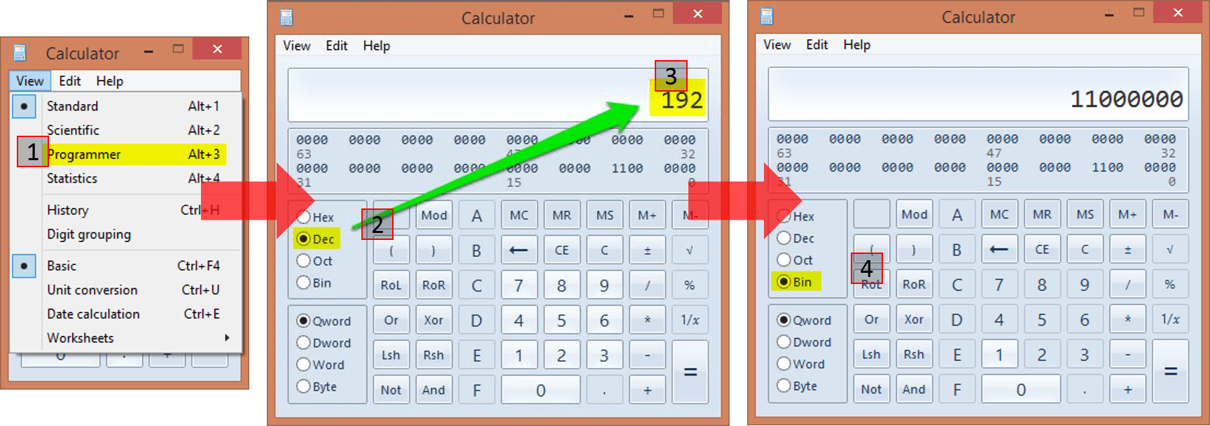
Let’s look at what this gives us. We compare the subnet mask against the IP address. From this comparison, we can determine which part of the IP address describes the network and which describes the actual host. All you have to do is look at the Binary column in the table, and it should be pretty obvious. For each position in the IP address that lines up with a 1 in the subnet mask, that is part of the network. Each position in the IP address that lines up with a 0 in the subnet mask represents part of the host’s address. So, we now know that this host will consider every single other host whose IP starts with 192.168.0 to be on the same network. It considers itself to be the host with the number 10, and other hosts on that network will be numbered 1 through 9 and 11 through 254. 192.168.0.0 represents the IP address of the network (host ID of all 0s) and 192.168.0.255 is the broadcast address for that network (host ID of all 1s). See? Just by being able to tell the difference between a 0 and a 1 (and maybe how to use Calc.exe to convert from decimal to binary), you figured out the networking details for this computer.
In case you don’t know how to use Calc.exe, let me help you:
 If you do this a lot, you can set yourself up with a PowerShell script to do it even more quickly.
Classless Inter-Domain Routing (CIDR)
We used a Class C subnet mask because it falls along octet boundaries which makes it easier on the eyes (and maybe the brain), but the basic pattern is established here. A subnet mask always begins with a 1 and always (well, almost always) ends with a 0. There is always an unbroken line of 1s and (almost) always a following line of unbroken zeros. What makes this “almost” is that 255.255.255.255 is a valid subnet mask, so sometimes the zeros won’t be there. However, in no case can the line of 1s and the line of 0s ever intermingle.
As we found out pretty quickly, trying to break everything up into hard-line classes of A, B, or C ran us out of valid networking combinations pretty quickly. So, the idea of “classless” IPs was born. This is very simple: it just means that the network/host breaks don’t necessarily fall inline with neat octet boundaries. People get scared here, because now you see subnet masks like 255.255.248.0, and most people can’t immediately parse what that means. Keep calm, and calc on:
255.255.248.0 = 11111111.11111111.11111000.00000000.
Just line that up against your IP, and you know exactly what’s going on. For simplicity’s sake, let’s just use the same 192.168.0.10 that we started with.
| Decimal | Binary | Hexadecimal | |
|---|---|---|---|
| IP Address | 192.168.0.10 | 11000000.10101000.00000000.00001010 | C0.A8.00.0A |
| Subnet Mask | 255.255.248.0 | 11111111.11111111.11111000.00000000 | FF.FF.F8.00 |
This is a little less fun than the previous edition because again, we have a network section of 192.168.0.0, but the host portion is now 0.1 instead of just 1. It’s effectively indistinguishable from the Class C description. For that, we use CIDR notation. This just appends /xx to the end of the network and means nothing more than the total number of 1s used in the subnet mask. So, the network is 192.168.0.0/21 (1 full octet of 8 + 1 full octet of 8 plus 1 partial octet with 5, 8 + 8 + 5 = 21). It’s also nice because we can express an entire IP address this way as well: 192.168.0.10/21 means the same thing as 192.168.0.10 with a subnet mask of 255.255.248.0. What’s changed from the Class C example is the scope of our network. Instead of it stopping at FF in the final octet, it stops at 00000111.11111111 in the final two octets. So, the broadcast address in 192.168.0.0/21 is 192.168.7.255. The valid range of host addresses for this network is 192.168.0.1 through 192.168.7.254. If you don’t understand at this point, it’s not because you’re not smart enough, it’s because you’re over-thinking it. You’re letting those little dots get in the way of comprehension. All that you need to do to figure out what IPs fit in the same network is to determine how far you can go without modifying a number that’s blocked off by a 1 in the subnet mask. This is why most of us work this stuff in binary. It’s actually easier.
Pre-CIDR, that example would have probably been called “supernetting”. We took a Class C range and made it bigger. The traditional /24 break would have meant networks of 192.168.0.0/24, 192.168.1.0/24, 192.168.2.0/24, and so on. In the case of our /21, the next network is 192.168.8.0/21, then 192.168.16.0/21, etc. When we first started doing all this stuff, subnetting was more common. We would take a Class C range and make it smaller, as in converting it to a /25. Doing this, we could split out networks into smaller chunks, and then we’d have, perhaps, a server IP network and a desktop IP network, etc. You get the idea. Sub/supernetting is really not what I want to talk about here, I just want you to understand what the subnet mask does.
Putting the Subnet to Practical Use
As I said before, the subnet has exactly one practical purpose. That’s for the sending host to determine whether or not the destination host is on the same network. That’s all it does. Pay attention here: this is a one-way calculation. It only comes into play in the send operation.
Example 1
Let’s start with an easy one. My desktop computer’s IP is 192.168.25.55/24. I want to talk to a computer with IP address 192.168.25.37. Here’s the process:
| Decimal | Binary | |
|---|---|---|
| Source IP Address | 192.168.25.55 | 11000000.10101000.00011001.00110111 |
| Destination IP Address | 192.168.25.37 | 11000000.10101000.00011001.00100101 |
| Subnet Mask | 255.255.255.0 | 11111111.11111111.11111111.00000000 |
| Source Network | 192.168.25.0 | 11000000.10101000.00011001.00000000 |
| Destination Network | 192.168.25.0 | 11000000.10101000.00011001.00000000 |
| Source Host | 55 | 00110111 |
| Destination Host | 37 | 00100101 |
The source host looks at the source network and the destination network and realizes they’re the same. How does it know this? By lining up the subnet mask against the source and the destination network:
| Position | 1 | 2 | 3 | 4 | 5 | 6 | 7 | 8 | 9 | 10 | 11 | 12 | 13 | 14 | 15 | 16 | 17 | 18 | 19 | 20 | 21 | 22 | 23 | 24 | 25 | 26 | 27 | 28 | 29 | 30 | 31 | 32 |
|---|---|---|---|---|---|---|---|---|---|---|---|---|---|---|---|---|---|---|---|---|---|---|---|---|---|---|---|---|---|---|---|---|
| Source | 1 | 1 | 0 | 0 | 0 | 0 | 0 | 0 | 1 | 0 | 1 | 0 | 1 | 0 | 0 | 0 | 0 | 0 | 0 | 1 | 1 | 0 | 0 | 1 | 0 | 0 | 1 | 1 | 0 | 1 | 1 | 1 |
| Destination | 1 | 1 | 0 | 0 | 0 | 0 | 0 | 0 | 1 | 0 | 1 | 0 | 1 | 0 | 0 | 0 | 0 | 0 | 0 | 1 | 1 | 0 | 0 | 1 | 0 | 0 | 1 | 0 | 0 | 1 | 0 | 1 |
| Subnet Mask | 1 | 1 | 1 | 1 | 1 | 1 | 1 | 1 | 1 | 1 | 1 | 1 | 1 | 1 | 1 | 1 | 1 | 1 | 1 | 1 | 1 | 1 | 1 | 1 | 0 | 0 | 0 | 0 | 0 | 0 | 0 | 0 |
If there is any variance at any point of either address in the columns that line up against the leading march of 1s in the subnet mask, then the source and destination IPs are on different networks. It’s that simple.
Example 2
Let’s look at a “harder” one.
192.168.1.42/25 wants to talk to 192.168.37.42.
| Decimal | Binary | |
|---|---|---|
| Source IP Address | 192.168.1.42 | 11000000.10101000.00000001.00101010 |
| Destination IP Address | 192.168.37.42 | 11000000.10101000.00100101.00101010 |
| Subnet Mask | 255.255.255.128 | 11111111.11111111.11111111.10000000 |
| Source Network | 192.168.1.0 | 11000000.10101000.00000001.00000000 |
| Destination Network | 192.168.37.0 | 11000000.10101000.00100101.00000000 |
| Source Host | 42 | 00101010 |
| Destination Host | 42 | 00101010 |
We can (hopefully) see right away that the source and destination networks are different. So, the sender will need to go through a router. The fact that the host numbers are identical is irrelevant.
Getting to a Router
For our second example, we understand that we need to find a router. How do we do that? Well, you’ve probably filled out an entry for a “default gateway” a few hundred or thousand times in your career. But have you ever thought much about it? Here’s a dump of the routing tables on my system, restricted to IPv4 and the adapter that gets my onto my live network:
PS C:> Get-NetRoute -AddressFamily IPv4 -InterfaceIndex 3 | Format-Table DestinationPrefix, NextHop

DestinationPrefix                                           NextHop
-----------------                                           -------
255.255.255.255/32                                          0.0.0.0
224.0.0.0/4                                                 0.0.0.0
192.168.25.255/32                                           0.0.0.0
192.168.25.55/32                                            0.0.0.0
192.168.25.0/24                                             0.0.0.0
0.0.0.0/0                                                   192.168.25.1
The DestinationPrefix column defines target networks for outbound networks. Starting at the top and working our way down, we begin with 255.255.255.255/32. 255.255.255.255 is THE broadcast address for TCP/IP. Any adapter that receives a packet with that IP as the destination should process it. So, this first entry says that if any packet appears with a destination address that perfectly matches 255.255.255.255 (the /32 means “identical match”, remember?), then that packet should be processed by 0.0.0.0 (that’s what NextHop means). 0.0.0.0 is nowhere, so it effectively means “process here, do not forward”.
Next we see 224.0.0.0/4. This is for multicast and is beyond the scope of this article. However, it is basically handled the same way as 255.255.255.255/32, except that it applies to any packet destined to 224.0.0.0/4.
Based on our discussion above, do you recognize the significance of 192.168.25.255/32? This is the broadcast address for the 192.168.25.0/24 network. So, this line says, “any packet with a destination IP address that perfectly matches 192.168.25.255 should be processed here”.
Next, we see 192.168.25.55/32. 192.168.25.55 is the IP address on this adapter. You might be wondering why this line is necessary. Basically, the IP versus subnet mask is calculated on every single packet that touches an adapter, no matter what. So, since the IP of this system is 192.168.25.55, then if I ping 192.168.25.55, 255.255.255.255/32 is the only matching subnet mask, and due to this entry our adapter knows that means “process here”.
192.168.25.0/24 should also be familiar, as it is the network that this adapter is a member of. This is a bit trickier than the entries above. What’s going to happen is that it’s going to be processed on this adapter, but if it doesn’t match the local adapter’s address and it’s not intended to be outbound, then it will be discarded. In a switched network, this doesn’t happen a lot, but it’s very common on networks that use hubs. If it is intended to be outbound, then it will be delivered into the local network. Either way, the “process here” still applies, hence the 0.0.0.0 hop entry.
The last and final entry is where routing comes into play. The rules are applied in a top-down fashion, so any packet that gets to this point can be considered “none of the above”… hence, default gateway. So, any packet that hasn’t already been trapped will be passed off to the device with an IP address of 192.168.25.1 for it to deal with. Hopefully, that device is a router, otherwise that traffic is going nowhere.
So, now that we’ve read that list in techno-speak, let’s read it in English.
- Is this a general broadcast packet (255.255.255.255/32)? If yes, I’ll process it. If not, send it to #2.
- Is this a multicast packet (224.0.0.0/4)? If yes, I’ll process it. If not, send to #3.
- Is this a local broadcast packet (192.168.25.255/32)? If yes, I’ll process it. If not, send it to #4.
- Is this packet addressed to me (192.168.25.55/32)? If yes, I’ll process it. If not, send it to #5.
- Is this packet destined for the local network (192.168.25.0/24)? If yes, I’ll process it. If not, send it to #6.
- Whatever this is, it is not my problem. Send it to the gateway (192.168.25.1).
We can sort of ignore the first four rules and focus on the last two. Essentially, if it’s on the same network, we’ll process it on the same network (rule #5). Otherwise, we kick it to a gateway. We can insert specific gateways, if we like. For instance, I might have an isolated network that sits behind a different router, say, a secured file server that holds data I want to be accessible to my home computers but to not have any route of its own out to the Internet. Let’s say I make that network 192.168.100.0/24. The router that connects my 192.168.25.0/24 network to that one has an IP address of 192.168.25.2. To make that work, I need to tell my adapter that packets destined to 192.168.100.0/24 need to go to 192.168.25.2. The PowerShell is like this:
New-NetRoute -DestinationPrefix 192.168.100.0/24 -InterfaceIndex 3 -NextHop 192.168.25.2
My route dump now looks like this:
PS C:> Get-NetRoute -AddressFamily IPv4 -InterfaceIndex 3 | Format-Table DestinationPrefix, NextHop

DestinationPrefix                                           NextHop
-----------------                                           -------
255.255.255.255/32                                          0.0.0.0
224.0.0.0/4                                                 0.0.0.0
192.168.100.0/24                                            192.168.25.2
192.168.25.255/32                                           0.0.0.0
192.168.25.55/32                                            0.0.0.0
192.168.25.0/24                                             0.0.0.0
0.0.0.0/0                                                   192.168.25.1
The placement of the rule for 192.168.100.0/24 means that if something needs to go through that gateway, it will be processed before the default gateway. The placement of the default gateway in the last rule literally means that it’s the “gateway of last resort”. If it can’t deal with the packet, then the packet is doomed.
How IP Interacts with Ethernet, Part 2
After all that, now we get to circle back to the beginning. What does process at “0.0.0.0” really mean, anyway? It means that the local adapter can’t just send this on to a gateway. It has to deal with it on it’s own. So, what it will do is decide if it’s going to keep the packet or not. Even though it might seem obvious to you if a packet is inbound or outbound, computers really aren’t that smart. They have to calculate the direction of the packet. So, if it’s got a packet that matches on a 0.0.0.0 rule, the next thing it will do is compare the source and destination addresses. If the source is not the local IP, then it’s inbound. The adapter will discard the frame if the destination indicates that it’s not meant for this host, or it will send the packet up to layer 4. If the source is the local IP, then it will send it down to layer 2 for Ethernet processing.
Here, then, is where it gets interesting. If the destination is the local subnet, then the layer 2 portion of this process needs to go out and get the MAC address that corresponds to that IP address. This is where ARP comes into play. I don’t know if there’s any built-in command-line way to go out and resolve an IP to a MAC address, but Windows does cache entries. So, if you have communicated with any given IP address, then you can ask Windows for its MAC:
C:UsersEric>ping 192.168.25.10

Pinging 192.168.25.10 with 32 bytes of data:
Reply from 192.168.25.10: bytes=32 time=49ms TTL=128
Reply from 192.168.25.10: bytes=32 time=6ms TTL=128
Reply from 192.168.25.10: bytes=32 time=2ms TTL=128
Reply from 192.168.25.10: bytes=32 time=1ms TTL=128

Ping statistics for 192.168.25.10:
    Packets: Sent = 4, Received = 4, Lost = 0 (0% loss),
Approximate round trip times in milli-seconds:
    Minimum = 1ms, Maximum = 49ms, Average = 14ms

C:UsersEric>arp -a 192.168.25.10

Interface: 192.168.25.55 --- 0x3
  Internet Address      Physical Address      Type
  192.168.25.10         a0-b3-cc-e4-ef-bb     dynamic
What happened when Windows was assembling the frame for the PING packets was that it went out and got the MAC address for the adapter that’s using 192.168.25.10. It then built the Ethernet frame with a source MAC address of the local adapter and a destination MAC address of a0-b3-cc-e4-ef-bb. Then, it kicked it out onto the physical network for the switch to deal with.
OK, so now we understand local traffic. What about non-local traffic? Take a look at this:
C:UsersEric>ping www.altaro.com

Pinging www.altaro.com [64.91.230.229] with 32 bytes of data:
Reply from 64.91.230.229: bytes=32 time=36ms TTL=119
Reply from 64.91.230.229: bytes=32 time=36ms TTL=119
Reply from 64.91.230.229: bytes=32 time=55ms TTL=119
Reply from 64.91.230.229: bytes=32 time=36ms TTL=119

Ping statistics for 64.91.230.229:
    Packets: Sent = 4, Received = 4, Lost = 0 (0% loss),
Approximate round trip times in milli-seconds:
    Minimum = 36ms, Maximum = 55ms, Average = 40ms

C:UsersEric>arp -a 64.91.230.229
No ARP Entries Found.
What? How can this be? How can we communicate with that destination IP without its MAC address? The answer is, “It’s not our problem”. Whose problem is it? See for yourself:
C:UsersEric>arp -a 192.168.25.1

Interface: 192.168.25.55 --- 0x3
  Internet Address      Physical Address      Type
  192.168.25.1          a8-39-44-20-0d-d0     dynamic
TCP/IP knew that 64.91.220.229 wasn’t on the local subnet. There’s no specific route entry that matches 64.91.220.0/24, so it bubbled down to the gateway of last resort. That gateway is 192.168.25.1. So, while the TCP/IP packet kept its source of 192.168.25.55 and its destination of 66.91.220.229, the Ethernet frame used the MAC address of the local adapter but a destination MAC address that belongs to the router. Once the router received the packet, it stripped off the Ethernet frame and made a new one with a destination MAC address of the next router in the series and its own source MAC address. Now, I know some of you are about to compose a nastygram about the network designation of 64.91.220.0/24, but you need to wait until after the next section. For completeness, my router also performs network address translation, so it would have also replaced the source IP address with its own, but that’s beyond the scope of this article and unnecessary knowledge for the comprehension of basic TCP/IP routing.
The Return Trip
So, we know that almost all TCP/IP communications is two way. You request a web page, you receive a web page. You copy a file, you get acknowledgement. Etc. But, there is really no such thing in TCP/IP as “return traffic”. Packets are sent and packets are received. They aren’t really “returned”. So, what can, and does, happen is that you can send to a host but it can’t send to you. If you ever take a TCP/IP exam, there will probably be lots of sample configurations in which they’ll ask you which computers can talk to which other computers, based solely on IP addresses and subnet masks. I can pretty much promise you that you’ll have multiple situations where Computer A can send to Computer B, but Computer B can’t send to computer A, all over a subnet mismatch. When I said above that my system just knows that 64.91.220.0/24 is a network other than its own, that’s because as far as it’s concerned, 255.255.255.0 is the only subnet mask that matters in the whole world and the only two networks that exist are 192.168.25.0/24 and that other network that isn’t 192.168.25.0/24. The actual network that 64.91.220.229 lives in is something for the host with IP 64.91.220.229 to be concerned with. When that system “replies” to a packet that I sent it, it has to go through the exact same process of figuring out if I’m on it’s local subnet and if not, which router to send it to.
TCP/IP and VLANs
I need to take a brief detour here and talk about VLANs. Because of the way network engineers tend to build things, a lot of non-networking people come away believing that VLANs and IP subnets have some relation. They do not. If I put 192.168.3.10/24 in VLAN 2 and 192.168.3.11/24 in VLAN 3, those adapters will never be able to talk to each other. Their adapters will try to reach each other using the local Ethernet broadcast network, but they exist in different Ethernet broadcast networks. Putting a router in won’t help, because routers will think they’re both on the same subnet. IP addresses are a layer 3 component and VLANs are a layer 2 component. Routers don’t actually cross VLANs, either. Routers only cross IP subnets. What happens, though, is that network engineers will give routers a layer-2 presence in a particular VLAN and give it an IP address that shares a subnet with the other devices in that VLAN, which gives the appearance that what the router is doing is sending from one VLAN to another. While technically true, all it’s doing is moving traffic from one IP subnet to another. This could just as easily be done without using VLANs at all. The purpose of VLANs is to wall off these Ethernet broadcast networks to cut down on the effects of Ethernet broadcasts and to guard against network breaches that work at layer 2.
Application to Hyper-V
Overall, Hyper-V is oblivious to layer 3 and IP addresses. Hyper-V Network Virtualization is more or less a layer 3 operation, but the parts that really matter come in VMM’s extensions, not so much with Hyper-V’s innate powers. Without a basic understanding of how IP addressing works, the function of the Hyper-V switch and the configuration of Hyper-V hosts, especially in a failover cluster, is far more confusing than it needs to be.
What’s Next
From here, we’re going to move on from basic theory into technologies that are more Hyper-V centric. We’ll start with link aggregation and teaming.
Have any questions?
Leave a comment below!
Backing up Hyper-V
If you’d like to make backing up your Hyper-V VMs easy, fast and reliable, check out Altaro Hyper-V Backup v4. It’s free for up to 2 VMs and supports Hyper-V Server 2012 R2! Need more? Download a 30-day trial of our Unlimited Edition here: http://www.altaro.com/hyper-v-backup/.
(Don’t worry, we hate spam too!)


Not a DOJO Member yet?
Join thousands of other IT pros and receive a weekly roundup email with the latest content & updates!
More in this category


About the Author

Eric Siron


13 thoughts on "Hyper-V and Networking – Part 3: IP Routing"
Brilliant article! That is all.
Very Good Article with one of the best explanation. Good work.