In this article, I’ll be taking you through the virtual machine settings dialog in Hyper-V Manager, which is by far the most complex and detailed component of the application.
If you haven’t yet read the previous articles in this set around Hyper-V Manager, I recommend you do so:
- How to set up Hyper-V Manager for Remote Management of Hyper-V
- How to set up Host Configuration in Hyper-V Manager
You will need to have gotten connected to a host and created at least one virtual machine (instructions in the previous article) before you can use the knowledge in this article.
How to Access the Settings Dialog
The Settings dialog is reached through the context menu for a virtual machine. The two ways to gain access to the context menu are by right-clicking the virtual machine or by highlighting the virtual machine in the list so that its context menu appears in the lower portion of the right pane of Hyper-V Manager:
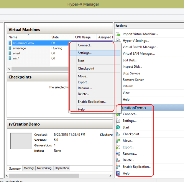
Just click Settings from the context menu, and you’ll be presented with the settings dialog for that virtual machine:
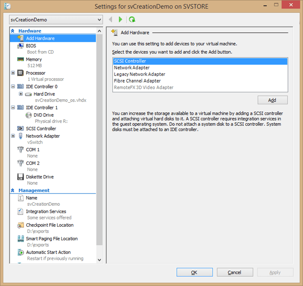
The left side is a series of tabs and sub-tabs that contain all the settings available in Hyper-V Manager to control a virtual machine. The following sections will cover each of these tabs and their settings in detail.
Add Hardware
The purpose of this tab is fairly self-explanatory: it allows you to add virtual hardware to the virtual machine. The options will be different depending on whether or not you’re working with a Generation 1 or 2 virtual machine, because a Generation 2 virtual machine cannot use emulated hardware. The preceding screenshot is from a Generation 1 virtual machine. The options available to you are:
- SCSI Controller: In 2012 R2, virtual machines should always be automatically created with at least one SCSI controller. Each controller can have up to 64 attached virtual devices (hard disks or CD/DVD drives). If that number proves to be insufficient, you can continue adding SCSI controllers up to a maximum of four.
- Network adapter: This adapter is a “synthetic” adapter, meaning that it uses Hyper-V’s VMBus to efficiently handle network traffic. It is invisible to guest operating systems that are not aware of Hyper-V (Windows versions prior to Vista, Windows Server versions prior to 2008, and many non-Microsoft versions). If the guest operating system can install Hyper-V’s integration services, then it can use this network adapter.
- Legacy network adapter: The legacy adapter is “emulated”, which means that Hyper-V creates an artificial network adapter that exposes the same software functions as a standard physical adapter that nearly any guest operating system should be able to recognize. This adapter is not very efficient, but works when the synthetic adapter does not. It is the only adapter that Generation 1 virtual machines can use to PXE boot from. The legacy adapter is not available for Generation 2 virtual machines.
- Fibre Channel Adapter: The virtual fibre channel adapter allows you to connect a virtual machine directly to fibre channel storage. It requires a physical fibre adapter that supports NPIV (node port ID virtualization) to be installed in the host in order to function. Unlike the SCSI adapter, the virtual fibre adapter allows the virtual machine to connect to actual hardware reachable by the physical adapter.
- RemoteFX 3D Video Adapter: In order to use RemoteFX in a guest machine, the physical system must be configured as a Remote Desktop Virtualization Host and it must have a physical video unit that supports DirectX 11 or later with a WDDM 1.2-compatible driver. Adding this virtual adapter allows the virtual machine to utilize the advanced graphics capabilities of the physical adapter.
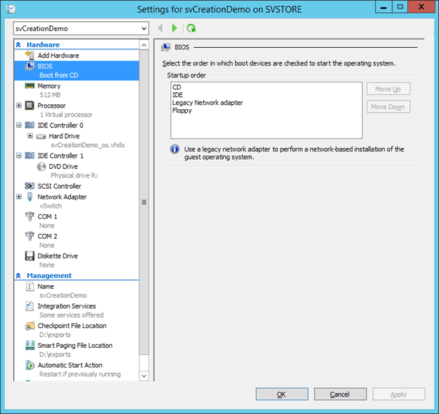
BIOS (Generation 1 VMs Only)
This screen’s only function in 2012 R2 is to establish boot order for the virtual machine. The possible boot sources are contained in the list box. You can highlight one and use the Move Up or Move Down buttons to place it in the desired priority order. When booted, the virtual machine will attempt to start from the topmost item and work its way down until it finds a bootable device.
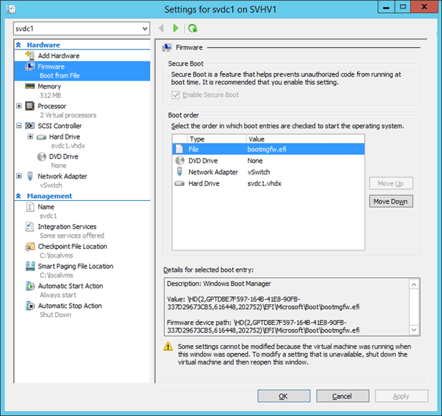
Firmware (Generation 2 VM Only)
The corollary to the BIOS tab for Generation 2 virtual machines is the Firmware tab. The first item on this page is Secure Boot. This is a feature that helps to ensure that the boot image of a virtual machine’s operating system has not been tampered with. With 2012 R2, this only works with Windows 8 or later and Windows Server 2012 and later.
The next section of the dialog page is a boot priority list, same as on the Generation 1 and works the same way. The only real difference is the addition of the details display at the bottom that provides additional information about the highlighted boot item.

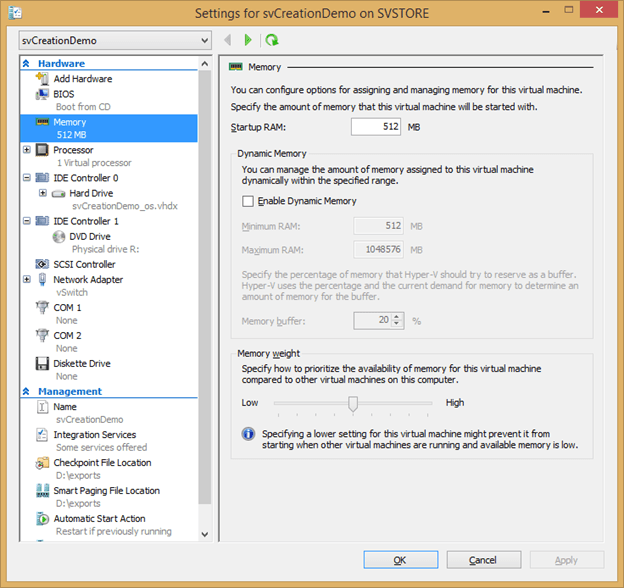
Memory
The Memory tab controls the way that physical memory is allocated to the virtual machine. Remember that memory is not a shared resource in the way that CPU is, so memory dedicated to a specific guest is unusable for any other purpose while that guest is turned on.
The first option is Startup Memory. This is one of the more important settings on the page. For guests that do not – or cannot – use Dynamic Memory, this number represents the entire amount of memory that the guest will have available. For guests that can use Dynamic Memory, this establishes how much they will have before their operating system loads and the Dynamic Memory driver takes control over memory allocation. The guest operating system will always believe that it has at least this much memory, and will use it for calculating any initial values that depend on the total quantity of memory (such as caches). This value cannot be changed while the virtual machine is active.
The first item in the Dynamic Memory section enables the feature for the guest. Remember that Dynamic Memory also requires that the guest have Integration Services installed and functional or the virtual machine will always be set at its Startup Memory value.
The first option in this section is for the Minimum RAM value. This establishes the lowest point that a virtual machine’s assigned memory can ever be dropped to. There is no guarantee that a virtual machine can actually be reduced to this amount of memory. The value can be lowered, but not raised, while the guest is online.
The second option is Maximum RAM, which sets the ceiling for the amount of memory that can be allocated to a guest. As with the minimum, there is no guarantee that this amount can be allocated to a guest. The maximum setting is 1 terabyte, which can be specified even if it exceeds the amount of physical RAM installed in the host. The value can be raised, but not lowered, while the guest is online.
The third and final option in this section is Memory buffer. This specifies the amount of memory that Hyper-V is to attempt to keep in reserve for increases to Dynamic Memory allocation. The indicated ten percent is a sliding value. It is calculated based on the amount of memory currently assigned to the guest. A guest using 1 gigabyte will have a 100 megabyte reserve. The same virtual machine at 2 gigabytes will have a 200 megabyte reserve. The purpose of the reserve is to accelerate the allocation of additional memory to satisfy guest requests. If total host memory capacity becomes low, these reserves may be sacrificed.
The last section of this dialog page is Memory weight. It contains only a slider control which allows you to set the memory assignment priority of the virtual machine. This is intended only to aid Hyper-V in resolving allocation when there is contention. Usually, this is at host startup. Several virtual machines may be starting at the same time, but there may not be enough memory for all of them. Virtual machines with a higher memory weight will be turned on first. If memory is freed up later (for example, through the use of Dynamic Memory), then virtual machines with a lower priority will be activated. This slider also establishes the priority order for Dynamic Memory allocation.
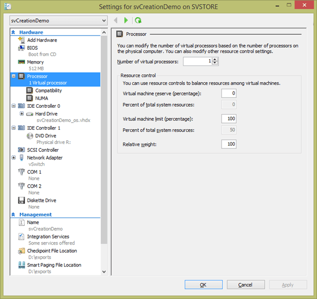
Processor
The Processor tab controls the virtual CPU settings for this VM. Before going through the items on the page’s screen, notice that there is a plus sign icon next to Processor in the left pane. If you click this, it will expand to display two sub-tabs that contain further options for the processor.
On the primary tab’s screen, you begin by choosing the number of virtual CPUs that the guest will have. This does not remove them from the host’s physical pool. Physical CPU resources are shared among all virtual machines. The number that you assign here sets the maximum number of threads that the virtual machine can schedule for processing simultaneously. They will be run on the next physical core that Hyper-V makes available.
The next option is Virtual machine reserve (percentage). This setting allows you to control a minimum amount of physical CPU that will always be available to this virtual machine. As you adjust it, notice that the Percent of total system resources indicator automatically adjusts to match. The effect of this setting depends upon how many physical cores are in the host machine and how many virtual CPUs you have assigned to the virtual machine. The calculation is:
number of virtual processors / number of physical cores * reserve percentage
The total reserve for all virtual machines cannot exceed 100 percent. If the total guest reserve does reach 100%, no further virtual machines can be turned on. This setting can be modified for a guest that is currently turned on.
The virtual machine limit is the reverse of the reserve. It sets a cap on CPU utilization by the virtual machine. The same calculation is used for the limit as for the reserve. As with the reserve, the limit can be changed for an active guest.
The final option on this page is Relative weight. You use this to adjust the priority in which virtual machines are assigned compute resources under contention. Guests with a higher weight will be given priority. Multiple guests can use the same setting. This will guide Hyper-V for both thread scheduling and determining which guests will be left off in the event that the total reserve exceeds 100%. The weight can be increased or decreased while the virtual machine is turned on.
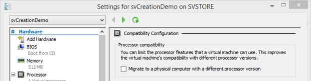
Processor: Compatibility
In 2012 R2, only a single setting remains on the processor compatibility tab. This is a checkbox that blocks the virtual machine’s access to some of the advanced capabilities of the physical CPU in order to enable it to Quick and Live Migrate between processors from different generations. This does not allow migrations between processors from different manufacturers.
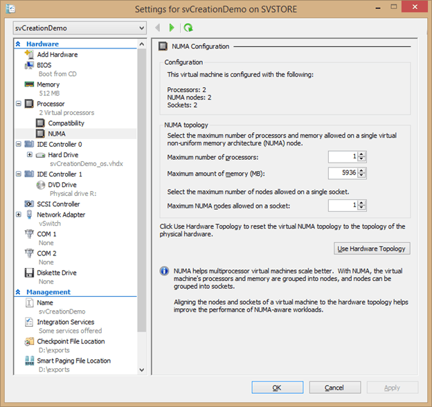
Processor: NUMA
NUMA stands for “Non-Uniform Memory Access”. It allows a processor to run threads whose memory is owned by that processor’s memory controller whenever possible instead of evenly distributing all threads throughout available cores. The concept itself will be explored more thoroughly in a later article. The NUMA-related settings are found on this sub-tab.
The first section, Configuration, simply shows the virtual machine’s current NUMA configuration. The second section, NUMA topology, is where you can make changes. Hyper-V cascades NUMA down from the host to make the topology visible to the guest and will select appropriate defaults. However, you’re free to override those defaults, and even cause Hyper-V to create a virtual NUMA topology.
The Maximum number of processors allows you to control how many virtual CPUs the guest can have in a single NUMA node. You can select up to 64 CPUs per NUMA node, even if neither the guest nor the host have that many vCPUs or cores. The Maximum amount of memory (MB) setting allows you to adjust the maximum size of any given NUMA node.
The final control on this page is Use Hardware Topology. This button allows Hyper-V Manager to detect the physical NUMA layout and apply it to the guest in a method that it determines to be optimal. Be aware that this may not return the guest to its default settings.
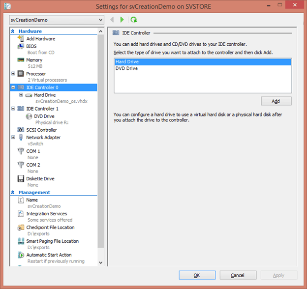
Hard Disk Controller
Virtual hard disk controllers come in two types: IDE (Generation 1 virtual machines only) and SCSI. Use them to attach hard disks and DVD drives to the virtual machine. Selecting the controller gives you the opportunity to add a new drive. These drives can be virtual or physical. Note: SCSI drives on Generation 1 virtual machines cannot host a DVD drive.
Hard Disks
Whether adding or editing a disk, the hard disk dialog tab looks the same.
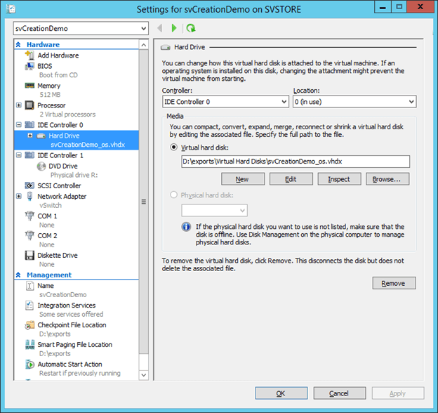
At the top, choose the controller and controller position that you wish the drive to be attached to. There are no restrictions regarding moving a disk between an IDE or SCSI controller, but Generation 1 virtual machines will only start from devices attached to an IDE controller.
After the controller selection, you’ll find the Media section which is where you detail the object that represents the hard disk. You can select a virtual hard disk file or a physical disk.
Virtual Hard Disk
This portion provides much more control than simply selecting a virtual hard disk. The New button allows you to create a new disk, using the same New Virtual Hard Disk wizard you find in the main Hyper-V Manager interface. Upon finalizing the creation, the new disk will be automatically attached at the designated location.
The Edit button allows you to make changes to a virtual hard disk that’s already attached. It initiates a wizard that guides you through the possible changes. The displayed options will change depending on the type of virtual hard disk that’s selected and the state of the virtual machine. The options are:
- Compact. This option is only displayed for dynamically expanding hard disks. Any disk blocks that were previously in use but have since been marked as deleted will be reclaimed and the file will be shrunk. Due to a bug, this option will be visible even when the owning virtual machine is online, but it will only be successful if nothing is using the virtual hard disk file.
- Convert. Choosing this option will allow you to change a VHD file to a VHDX file and vice versa and/or a fixed virtual hard disk into a dynamically expanding virtual hard disk and vice versa. This process does require the creation of a new disk, which will be created by reading the data from the source disk. You cannot perform this procedure while the disk is in use.
- Expand. Use the Expand feature to grow the maximum capacity of a virtual disk. This action can be taken while the virtual machine is online. For most guest operating systems, you will also need to perform an additional task to utilize the space. For Windows guests, you must extend the disk or create a new partition in newly created blank space.
- Merge. This option is only available for differencing disks. You’re given one of two options: you can merge the differencing disk into its parent completely or you can create a new disk that combines both. With either option, the differencing disk itself is destroyed and you must select a new one upon returning to the disk tab in the Settings dialog. Take care that you do not merge a disk that has children of its own, as they will be permanently orphaned.
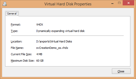
The Inspect button presents a small dialog with details about the file that constitutes the virtual hard disk. For dynamically expanding disks, the actual consumed space and its upper limit will be displayed. For differencing disks, the parent will be displayed.
Use the Browse button to direct this disk to use a different VHD or VHDX file than the one that is currently selected or to select the initial file for a new disk.
Physical Hard Disk
It’s no longer recommended to connect physical hard disks, known as pass-through disks to a virtual machine except in rare situations. However, if you have need of such a disk, use this radio button to attach it to your virtual machine. The disk that you use can be a physical disk local to the host or a LUN on remotely-attached storage. It must be offline before you can use it. If the Physical hard disk radio button is disabled, Hyper-V Manager does not detect any eligible storage. Detected disks will be displayed by their local LUN information:
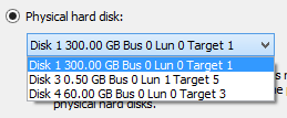
Once attached to the virtual machine, the disk or LUN cannot be used for any other purpose. The virtual machine will take control of the entire disk or LUN, including any partitions that it may contain.
Remove
The last control on this page is the Remove button. The only function this has is to remove the disk from the virtual machine’s controller. If it is a virtual hard disk, the file is left intact but the virtual machine is removed as an owner. If it is a physical disk, control is reverted to the management operating system and the disk is left in its original offline state. You can remove a SCSI disk from a virtual machine while it is online, but the guest must be offline to remove a disk from the IDE chain.
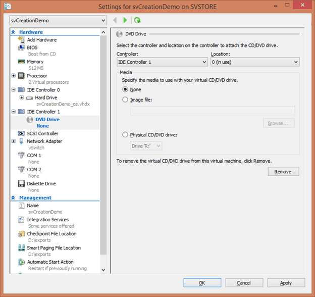
DVD Drives
As with hard drives, the DVD drives that you attach to a virtual machine can be virtual or physical. The media used for a DVD drive can be changed at any time whether the guest is running or not. The first portion of this dialog page is exactly like that for hard drives: choose the controller and location. Following that is also a Media section, but there are different options than for hard disks:
- None. With this option, the guest operating system will have an empty DVD drive.
- Image file. Selecting an ISO file will present it as a CD or DVD to the guest operating system.
- Physical CD/DVD drive (not available on Generation 2 virtual machines). When this option is selected, the indicated physical drive on the host is passed through to the guest. If the drive is empty, the guest sees an empty drive. If physical media is present, the guest will be able to use it as if it were its own.
As with hard disks, the last option on this tab is Remove. This will remove the drive from the virtual machine entirely.
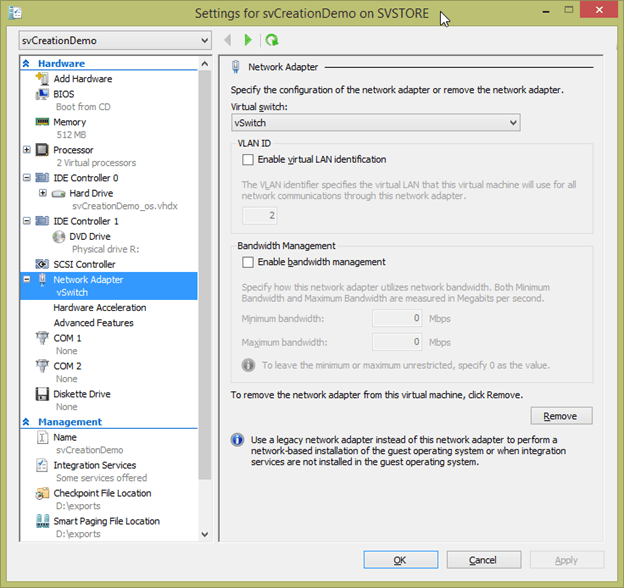
Network Adapter
As with the Processor tab, the Network Adapter tab has a plus sign icon next to it that, when clicked, will expand to show two additional sub-tabs: Hardware Acceleration and Advanced Features. As before, exploration will start on the primary tab. Before getting to that, take note of the “Network Adapter” text itself. This is the default name for the virtual adapter, and the only one that is possible to assign using the GUI. The name can be changed using PowerShell, so you might need to identify that an object is a virtual adapter by its icon, not the text.
A virtual adapter can only be added or removed while the virtual machine is off, but most of the settings can be changed while the guest is online.
The first item on this page is the Virtual switch selector. A Not connected option is always available, which is the virtual equivalent of unplugging the adapter entirely. All virtual switches on the host are displayed in the drop-down and the virtual machine can be relocated to any of them at any time.
The next section allows you to place the virtual adapter in a specific VLAN (virtual LAN). This follows the 802.1q standard for VLAN frame tagging in the Ethernet specification. The first option is this group is a checkbox, Enable virtual LAN identification, which enables tagging. If this is not checked, the virtual adapter receives and transmits only untagged frames. If the box is checked, you must then specify a number in the text box between 1 and 4096. The virtual adapter will receive and transmit frames with that tag. The Hyper-V virtual switch does allow for adapters with more VLAN settings, such as secondary VLANs and trunk mode, but these options are not available in the GUI.
The next section, Bandwidth Management, allows you to shape the traffic characteristics of this virtual adapter. While the GUI text does not change, the exact functionality of this screen depends on the virtual switch mode. If the virtual switch does not have bandwidth management enabled, then these boxes have no effect. If the virtual switch’s bandwidth management mode is Absolute, then the dialog works exactly as the text describes; the numbers you enter are for the minimum and maximum Mbps that the virtual adapter can pass. If the virtual switch’s bandwidth mode is Weight, then you will receive an error if you attempt to set the minimum to anything other than zero. The maximum will continue to work as indicated by the text. You must use PowerShell to adjust the minimum weight.
The final option on this tab is Remove. It permanently deletes the virtual adapter from the virtual machine. If you recreate it, the guest operating system will treat it like a new adapter.
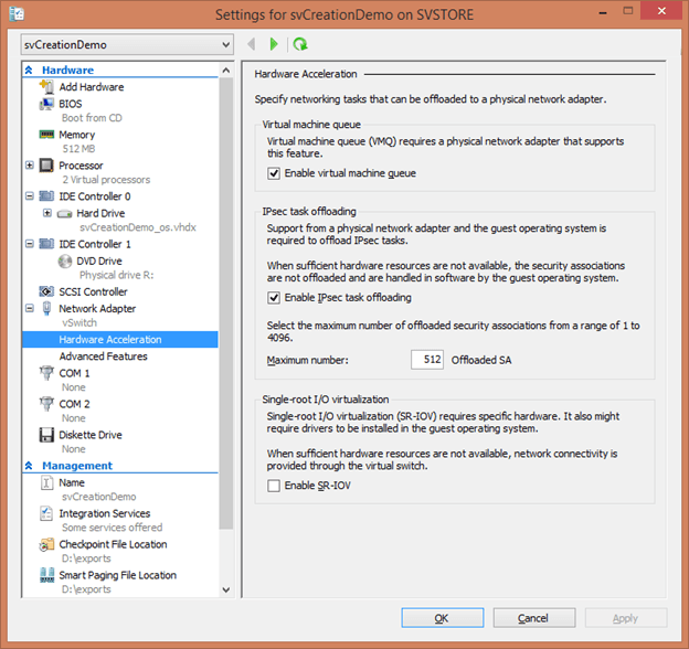
Virtual Adapter: Hardware Acceleration
The first virtual adapter sub-tab contains hardware acceleration settings. These are features of the physical network adapter that can enhance the performance of your virtual adapter. The first is Enable virtual machine queue. Virtual machine queue (VMQ) is an offloading technology that allows incoming traffic processing to be spread across multiple physical CPUs. This dialog entry allows you to prevent the specified virtual adapter from registering for a queue by unchecking the box.
The second section is related to IPsec task offloading. If the virtual adapter will be performing IPsec packet encryption and decryption, leaving the box checked allows it to offload this task to the physical adapter’s processor. As the text explains, the text box allows you to specify the maximum number of unique security associations the virtual adapter can offload. Any above this number will be processed inside the virtual machine.
The final option is for Single-root I/O virtualization. The technology itself will be discussed in the article on virtual networking. Checking this box causes the virtual adapter to attempt to use a virtual function on an SR-IOV-capable adapter that its virtual switch is assigned to. In order for this to work, the physical adapter must support SR-IOV, have an available virtual function, and the virtual switch must have been created with SR-IOV enabled.
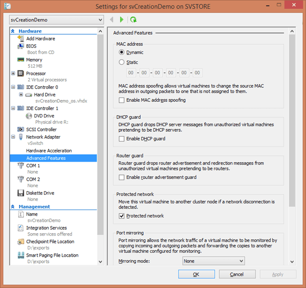
Virtual Adapter: Advanced Features
The Advanced Features sub-tab contains the remaining settings for a virtual adapter.
To start, you can configure a static MAC address for a virtual adapter if necessary. This allows you to ensure that Hyper-V doesn’t control or change it. Also in this section is a checkbox to Enable MAC address spoofing. If not checked, Hyper-V will not allow the guest operating system to override its MAC address.
The second section allows you to enable DHCP guard. This prevents the virtual adapter from receiving any DHCP discover or request packets, effectively preventing its operating system from acting as a DHCP server.
The third section performs the same function for routing requests. Checking Enable router advertisement guard prevents the virtual adapter from sending any frames advertising routing functionality from within the virtual machine.
The fourth section, Protected network, only applies to clustered virtual machines. If the host detects a failure on the virtual switch that this adapter is connected to, it will Live Migrate the virtual machine to another host.
The next section, Port mirroring, allows you to set the adapter as one of two ports in a mirror. By default, this setting is None, which means it functions as a standard adapter. You can set it to Source, which makes it the sender in a pair. If you set it to Destination, it will be the recipient adapter in a pair. When there is a Source and a Destination port mirror adapter on the same host, all packets that appear on the source adapter are replicated to the destination adapter.
The final option on this tab (not pictured) is Enable this network adapter to be part of a team in the guest operating system. When checked, the guest operating system can add this adapter into a team that uses link aggregation techniques to spread a single MAC address across multiple adapters. The guest operating system must support such a feature in order for this setting to be effective.
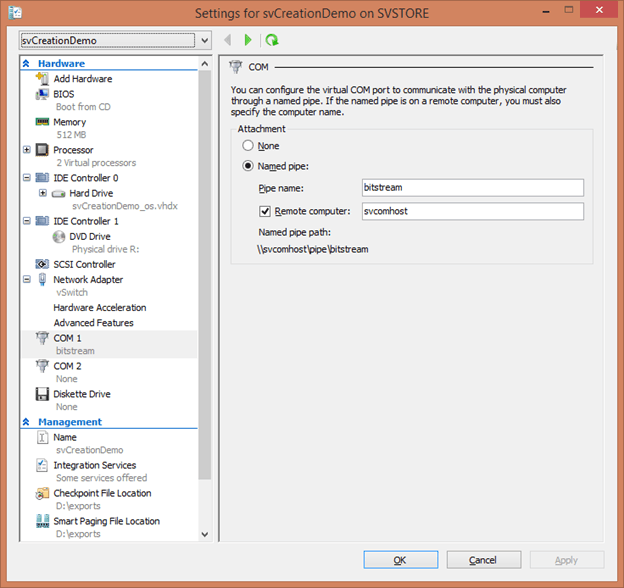
COM Adapters
Hyper-V provides minimal support for legacy COM ports to appear in a guest operating system. However, they can only be attached to a named pipe. The pipe must be available in the host operating system or on a remote computer that the host can reach. A Generation 1 guest has two COM ports that can be neither removed nor added to. Generation 2 guests cannot use this functionality.
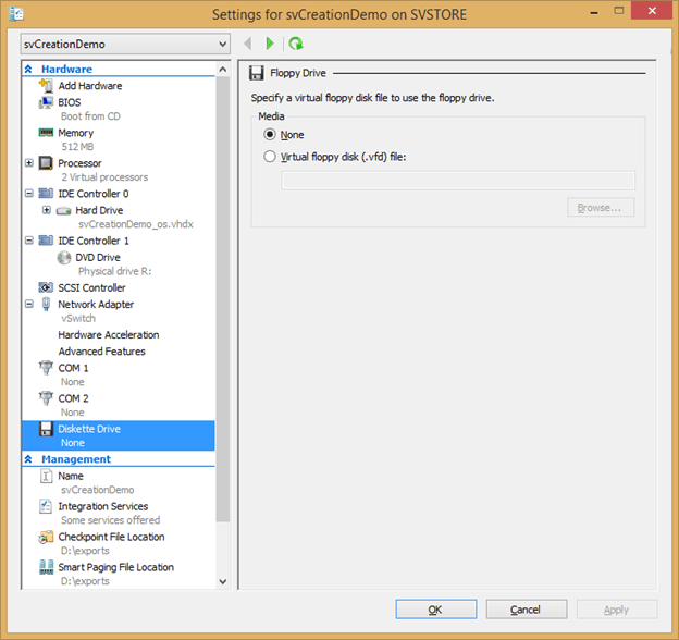
Diskette Drive
Virtual diskette drive functionality is only available to Generation 1 guests. Unlike hard drives or DVD drives, the diskette drive can only be virtual. The only file type that it recognizes is Microsoft’s VFD. These files can be created in the main Hyper-V Manager interface. You’ll find the links in the host’s action menu under the New submenu. A diskette drive file can be specified or removed at any time.
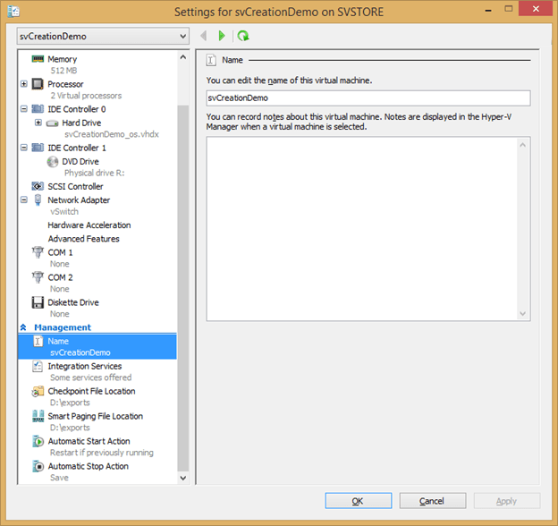
Name
The Name tab of the settings dialog box allows you to change the name of the virtual machine as it appears in Hyper-V Manager’s list. It does not affect the files that constitute the virtual machine nor is the guest operating system’s name affected in any way. This tab also allows provides a free-form text box for you to enter notes for a virtual machine. The name and notes can be modified while the guest is online.
Integration Services
All of the integration services will be thoroughly covered later on in this series. For now, just know that this is where you can enable or disable specific items. They are:
- Operating system shutdown
- Time synchronization
- Data Exchange
- Heartbeat
- Backup (volume checkpoint)
- Guest services
By default, all are enabled except Guest services. For any of them to work, integration services must be installed and available in the guest operating system. These settings can be changed while the virtual machine is online.
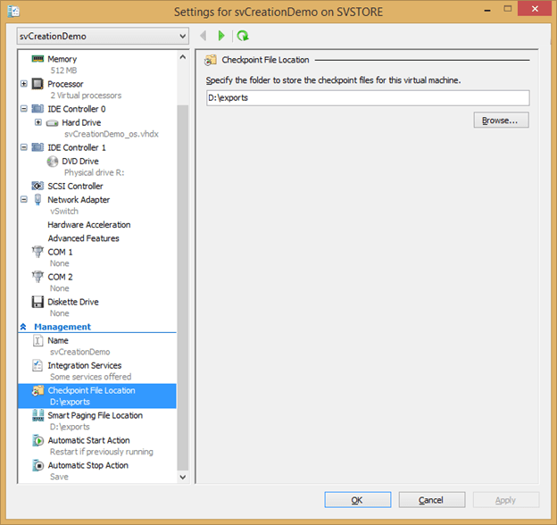
Checkpoint File Location
The Checkpoint File Location specifies where files will be created when the virtual machine is checkpointed. By specifying an alternative location, you can ensure that other virtual machines in a shared are not subjected to the potentially dangerous effects of a checkpoint that grows to the maximum capacity of the storage location. The location for new checkpoint files can be changed at any time, even if the guest is online. Only a Storage Live Migration procedure can move existing checkpoint files.
Smart Paging File Location
The Smart Paging File Location (dialog tab not shown) looks nearly identical to the Checkpoint File Location tab. Changing this setting allows you to control where Smart Paging files are placed in the event that the host needs to create them. The guest must be offline for you to be able to make changes to this location.
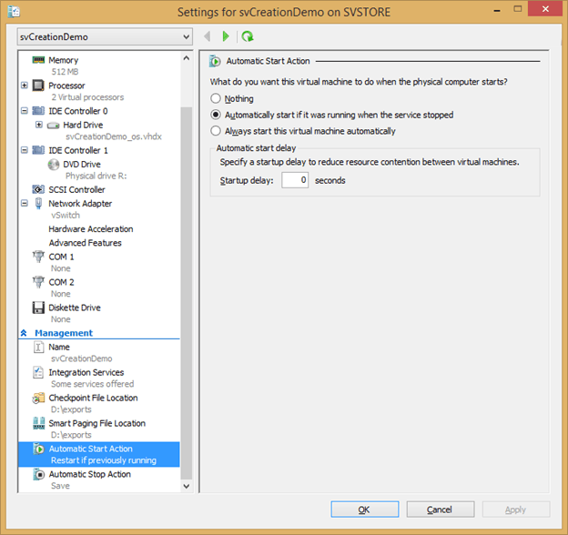
Automatic Start Action
The Automatic Start Action tab allows you to control how a virtual machine’s power state is handled when the host is booted. There are three possible options.
- Nothing leaves the virtual machine in the state it was left in at the time the host was powered down, typically Off or Saved.
- Automatically start it if it was running when the service stopped attempts to restore a previously running virtual machine to a running state. If the virtual machine was not on when the host was shut down, the virtual machine is left in its previous state.
- Always start this virtual machine automatically attempts to start the virtual machine regardless of its previous state. Additionally, there is a text box that allows you to specify a delay. This allows you to set a timer between the start of the hypervisor and attempts to boot this particular virtual machine. Because startup is a resource-intensive process, waiting a few seconds allows the virtual machines to spread out their startups. Virtual machines with Dynamic Memory may settle below a threshold that allows others to start more easily. You can also use this to help ensure that virtual machine with dependency services (such as Active Directory) are started before those that depend upon them, although Hyper-V cannot guarantee the timeliness of service starts within guest operating systems.
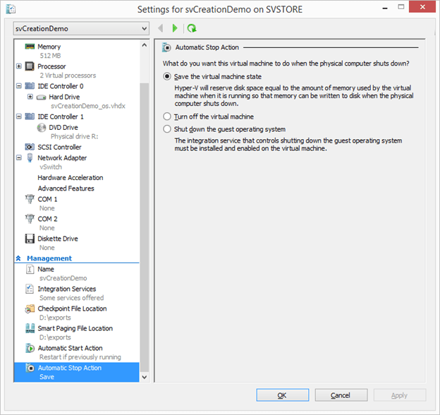
Automatic Stop Action
The Automatic Stop Action tab controls how a non-clustered virtual machine behaves when its host is shut down in an orderly fashion. These settings do not apply to clustered virtual machines; those will always be Live Migrated when possible and saved when not. As with the Automatic Start Action, there are three options:
- Save the virtual machine state saves the active contents of memory and running threads to the specified locations and turns the virtual machine off. This only requires as much time as is necessary to write the files to disk.
- Turn off the virtual machine performs a hard stop of the guest, much like pulling the power cord on a physical computer.
- Shut down the guest operating system performs an orderly shutdown of the guest. This can potentially leave the host blocked for an extended period of time.
These settings cannot be modified while the guest is online.
The End of the Tour
This completes our tour of Hyper-V Manager. If you worked straight through, you’ve now seen all of its screens and have a solid foundation for using GUI tools to manage your Hyper-V hosts and their virtual machines. You’ve also got a handy reference in case you need to locate a setting or get a brief reminder of what a particular item’s purpose.